
Flip-Flops: How They Work and What They Do
Flip-Flops: How They Work and What They Do
Author: Fucha
Reviewed by: Shiguang
Sooner or later, any explanation of how computers work must introduce one electronic device: the flip-flop. A flip-flop consists mainly of two vacuum tubes, with current flowing through one tube at a time. It has four terminals: two receive external pulses, and two deliver output pulses. The moment an external pulse arrives, the flip-flop “flips.” The tube that was conducting switches off, and current begins flowing through the other one. As the two tubes exchange roles, the flip-flop produces an output pulse.
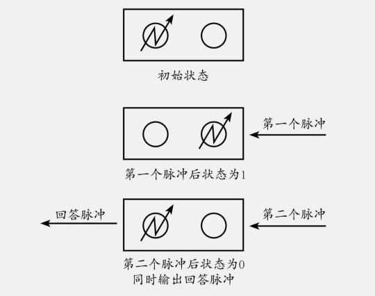
Now feed the flip-flop a continuous series of pulses and use one of the two tubes in Figure 1—the one on the right—to define its state. When the right-hand tube is not conducting, the flip-flop is in state “0.” When that tube conducts, the flip-flop is in state “1.”
Suppose the flip-flop begins in state “0,” with the right-hand tube off as shown in Figure 1. The first input pulse turns that tube on and flips the device to state “1.” It produces no output pulse yet because the left-hand tube has not begun conducting. When the second input pulse arrives, the left-hand tube conducts, the right-hand tube switches off, and the flip-flop returns to state “0” while producing an output pulse.
After two input pulses, the flip-flop is back where it started. A third pulse changes it to state “1,” a fourth returns it to state “0,” and the pattern repeats. In other words, its state cycles with a period of two pulses.
What happens when several flip-flops are connected? Take the three devices—Flip-Flops 1, 2, and 3—connected as shown in Figure 2. We send an input pulse to Flip-Flop 1, whose output pulse becomes the input to Flip-Flop 2. Its output then becomes the input to Flip-Flop 3. Flip-Flop 3 finally produces an output pulse of its own.

Now suppose five flip-flops are connected this way and all start in state “0.” We can write the state of the group as “00000.” Feed the first pulse into the rightmost flip-flop, and it changes to state “1.” Since it produces no output pulse, the other four remain in state “0,” giving us “00001.” On the second input pulse, the rightmost flip-flop returns to state “0” and sends an output pulse to its neighbor. That neighbor changes to state “1,” while the other devices receive no pulse and stay in state “0.” The combined state is now “00010.” When the third pulse arrives, the rightmost flip-flop changes back to state “1” without producing an output pulse. Nothing else changes, so the result is “00011.” Continue the cycle, and you get:
1 | State after pulse 1: 00001 |
Read those states as binary numbers and convert them to decimal, and the sequence becomes 1, 2, 3, 4, 5, 6, and so on. A chain of flip-flops can therefore “count” external pulses in its own distinctive fashion.
Binary notation represents every number with “0” and “1.” Each place in a binary number is worth 2 times the place to its right, rather than 10 times as much as in decimal notation. To convert a binary number to decimal, multiply each digit by 2 to the power n, where n is its place, and add the results. For “10011,” the calculation is 1 × 2^0 + 1 × 2^1 + 0 × 2^2 + 0 × 2^3 + 1 × 2^4 = 19.
Each change of state—one flip in response to one input pulse—takes only a few hundred-millionths of a second. Modern counting flip-flops can “count” more than ten million pulses per second, while the human eye needs about 0.1 seconds to distinguish a changing signal. The device is nearly one million times faster than we are.
Next, let us use flip-flops for addition. Connect three rows as shown in Figure 3. The first row represents the augend, the second the addend, and the third their sum. Whenever a flip-flop in either upper row is in state “1,” it sends a pulse to the corresponding device in the third row.
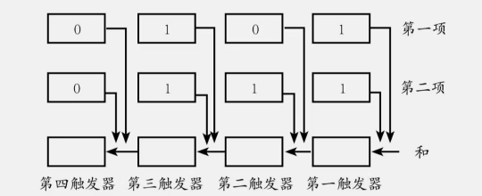
In Figure 3, the first two rows hold the binary numbers 101 and 111. The first flip-flop in the third row receives one pulse from each of the two devices above it, for a total of two. As we saw earlier, it remains in state “0” and sends one output pulse to the next flip-flop in its row. That second device also receives a pulse from the second flip-flop in the second row. With two pulses in all, it remains in state “0” and passes an output pulse to the third device. The third flip-flop receives that pulse plus one from each upper row, for a total of three. It ends in state “1” and produces another output pulse. The fourth flip-flop receives only that pulse, so it enters state “1.” That is binary addition. Written as a column calculation, it looks like Figure 4:
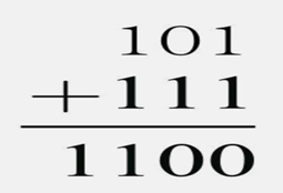
Converting the binary values in Figure 4 to decimal gives 5 + 7 = 12. The output pulses from the third row act as carries in column addition. With 20 or more flip-flops per row, the circuit can add numbers in the millions or even tens of millions. Modify the design, and it can handle not only addition and subtraction but multiplication and division as well.
Reference: Recreational Algebra
 爱发电(点击图片跳转)